−Table of Contents
Setting Up Development/Experimenting Environment
Using Breadboard
The breadboard is a mechanical base for electronics prototyping. Originally for this purpose was used the wooden board for cutting bread, that is why the name used now is the “breadboard”, also know as a solderless breadboard. It is because an electrical connection on this board can be made without soldering. Thus components can be reused, and changes to the circuit can be made easily.

On the front surface of the breadboard, many small holes are connected on the back of the board in a specific pattern using metal clips. These clips hold component leg or wire in place when they are put into the hole.
As the example, the circuit that contains the LED and resistance is taken.

Following the schematics, all the necessary components are connected in the right way using the breadboard.

Two side columns of the breadboard are made easily accessible from the rest of the breadboard and are commonly used for connecting the power to the circuit. Almost any DC (direct current) power source can be used to power the circuit, like batteries, Arduino board power pins, AC/DC regulators etc.
Two columns of 5 hole rows are used for connecting components. Extra connections can be made using wires. The gap in the middle allows using DIP (dual in-line package) circuits.
More information on breadboards can be found in the SparkFun webpage [1].
Soldering
Soldering is one of the essential skills in the world of electronics. The basic of electronics can also be a learner without the knowledge of how to solder; however, the soldering allows to work on more exciting projects and to join a wide range of electronics enthusiasts. This skill is essential because nowadays the electronic and electrical equipment is being used more often. The essential element of the knowledge about electronics is not only the ability to understand the working principles of the electronics but also the skill to build, repair and supplement the electronic devices.
Materials
The main soldering material is a solder. As the name of the material indicates, it is a compound of various soft metals and consumable materials, which is usually similar to a wire, wrapped in a reel or other easy-to-use packaging.

Different types of solder vary in diameter of the wire and the chemical composition. The type of solder that is used depends on the task.
According to the chemical composition, the solder is divided into two types: solder containing lead and lead-free solder. Historically, lead (Pb) is used in combination with tin (Sn) to ensure lower melting temperatures and better flow, which is essential for good contact between the parts.
Since 2006, many countries have forbidden using lead-containing solder, caring for the protection of nature and human health. When lead accumulates in the human body in significant amounts, it can cause poisoning. For this reason, it is important to remember – after using lead-containing solder, you should carefully wash your hands.
To avoid the risk of getting lead in the human body, the alternative is to use lead-free solder. Nevertheless few things need to be taken into account – the melting temperature of lead-free solder is higher and grip with other materials is lower. For improving the grip, flux can be used. Some solders already have flux in the core of the wire, so it is not necessary to buy them separately.
The diameter of the solder wire depends on the size of details that need to be soldered. The bigger the detail, the bigger the diameter of the solder wire.
Tools
Tools used for soldering are a soldering iron, stand for soldering iron, as well as different tools for removing solder and keeping parts together.
A soldering iron is an electrical heater that is used for heating the solder to it's melting temperature. As with all of the electrical devices, the instructions provided by the manufacturer should be followed when using the soldering iron. For specific tasks, there are also hot air and gas soldering irons. In this section, only the electric ones will be described.
There are different types of soldering irons so that they can be effectively used for diverse tasks. Soldering irons can vary in a shape of the tip, electrical capacity, heating temperature and control options. However, the primary indicator is the convenience of use. If the chosen soldering iron is too big, it will be difficult to solder small details. If it is too small, details probably will not get enough of the heat, and the solder will not stick properly to them. For beginners, it is advisable to use a soldering iron with a conical tip.

In addition to the soldering iron, there are several useful tools for soldering.
- Solder wick – used for desoldering, removes the extra solder out of the board or details, it absorbs the melted solder. The solder wick consists of multiple fine, interlaced lead threads.

- Solder vacuum – used for desoldering, removes the extra solder utilising a vacuum.

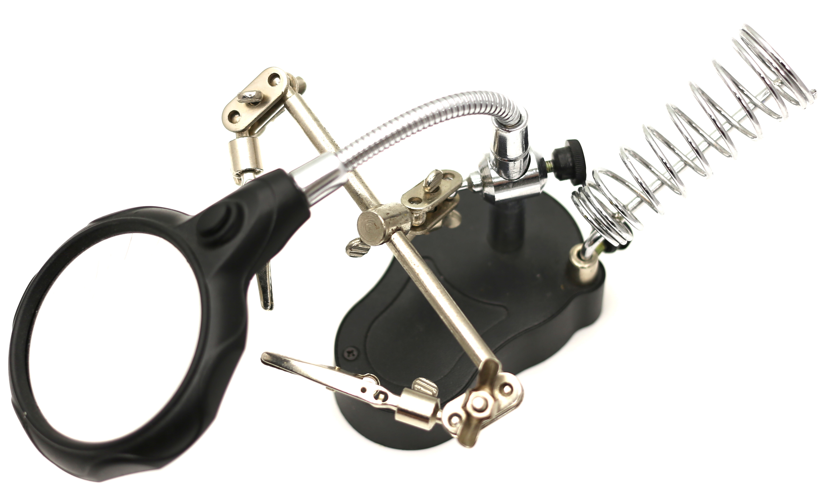
- Third-hand – a holder of details or other parts. It is especially useful for beginners.
Process of Soldering
It is not easy to describe the process of soldering in words, because it is connected with the kinesthetic skills of people and the paid attention. However, it is essential to follow several pieces of advice for good soldering.
- Be careful with the hot soldering iron!
- The working place should always be clean; it is advisable not to take a meal at the working place (because of the poisonous nature of the lead in the solder).
- It is advisable to use the third hand when it is possible.
- If possible, the temperature of the soldering iron should always be around 350 °C.
- If there is smoke coming from the soldering iron, the temperature should be decreased, or it should be turned off completely.
- Before soldering, a special soldering iron cleaner (wet sponge or special paste for cleaning the tip) should be used.
- The side of the soldering iron tip should be used when soldering rather than the very tip of it.
- The good contact can be ensured when heating simultaneously both components that are soldered.
- When the detail has been soldered, first the solder wire should be taken off and only then – the soldering iron.
- Good soldering of the detail with the board looks like a tip of the volcano rather than a ball or messy pile of solder.
In the Figure 9, the correct and incorrect soldering techniques are indicated.

