This is an old revision of the document!
−Table of Contents
7-segment LED display
Necessary knowledge: [HW] User Interface Module, [LIB] Delay, [LIB] 7-segment LED Display, [PRT] Light-emitting Diode
Theory
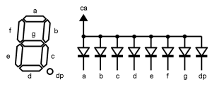
7-segmented LED number-indicator is a display which consists of 7 LED-s which are positioned as the shape of number 8. By lighting or switching off the corresponding LED-s (segments), it is possible to display numbers from 0 to nine and some letters also.
Electrically all anodes of the LED-s are connected to one anode pin ca. LED-s are lit by switching their cathodes (a, b, c…). To display numbers with several places, usually several number-indicators are being used. The indicators are equipped also with coma (point) segment dp. All in all one indicator has still 8 segments, but they are still called 7-segmented after the number of number-segments.
It is easy to use the LED number-indicators, because they can be controlled either directly from the pins of the microcontroller or through special drivers. There are different colors of LED number indicators; they can be very bright and very large. For displaying the entire Latin alphabet there are indicators with extra segments.
Practice
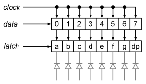
There is one 7-segment LED number-indicator on the board of digital module. It is controlled through a driver with serial interface A6275. The serial interface of the driver is similar to the SPI, where also clock signal and data signal are used. Different from SPI the chip-selection is not used there, but instead of it there is data latch function. The three lines mentioned are connected to the ATmega128 as follows:
- Latch-signal (latch) - PG2
- Clock-signal (clock) - PC7
- Data-signal (data) - PC6
The data is delivered by bits through the data pin. Every time the clock signal goes high, the contents of the shift-index is shifted to the right and the bit from the data-pin is read to the left most cell. So are 8-bits loaded to the shift-index. If the latch signal is set as high, the value of the shift-index is loaded to the latch-index where it stays until new loading. Each bit of the latch-index is connected through the current switching to one number-indicator’s segment. The segment is lit during the high bit-rate.
For displaying the numbers on the Home Lab’s digital module’s indicator, there is written following functionality to the library of the Home Lab.
//
// Set-up of the pins
//
static pin segment_display_latch =    PIN(G, 2);
static pin segment_display_data_out = PIN(C, 6);
static pin segment_display_clock =    PIN(C, 7);

//
// Marking card.
// The bits are marking the segments. Lower ranking is A, higher ranking is DP.
//
static const unsigned char segment_char_map[11] =
{
	0b00111111,
	0b00000110,
	0b01011011,
	0b01001111,
	0b01100110,
	0b01101101,
	0b01111100,
	0b00000111,
	0b01111111,
	0b01100111,
	0b01111001   // E like Error
};

//
// Start-up of the 7-segment indicator.
//
void segment_display_init(void)
{
	// Set latch, data out and clock pins as output
	pin_setup_output(segment_display_latch);
	pin_setup_output(segment_display_data_out);
	pin_setup_output(segment_display_clock);
}

//
// Displaying number on the 7-segment indicator.
//
void segment_display_write(unsigned char digit)
{
	unsigned char map;
	signed char i;

	// Check-up of the number
	if (digit > 9)
	{
		digit = 10;
	}

	// Number as the card of the segments.
	map = segment_char_map[digit];

	// Latch-signal off
	pin_clear(segment_display_latch);

	// Sending he bits. Higher ranking goes first.
	for (i = 7; i >= 0; i--)
	{
		// Setting the pin according to the value of the bit of the card.
		pin_set_to(segment_display_data_out, bit_is_set(map, i));

		// The clock-signal as high for a moment.
		pin_set(segment_display_clock);
		_delay_us(1);

		// The clock-signal as low.
		pin_clear(segment_display_clock);
		_delay_us(1);
	}

	// Latch-signal on.
	pin_set(segment_display_latch);
}
For displaying numbers and the letter “E”, there is created a constant array segment_char_map, where lighting of all 8 segments is marked with bit 1 and switch off is market with bit 0. The bits form higher to lower (from left to right in binary form) are marking segments DP, G, F, E, D, C, B, A. The control interface of the driver is realized with software SPI, i.e. by controlling the data communication pins as software in the program. All three pins are set as output with segment_display_init function. For displaying the sign is segment_display_write function, which finds the segment-card of the mark from the array and transmits all values of the segments bit by bit to the driver. The frequency of the clock signal is now with the software delays approximately 500 kHz.
The following is a little bit more concrete example program about the usage of number-indicator. The previously described function of the library is described in the program. The program counts numbers from 0 to 9 with approximate interval of 1 second. Such counting is achieved by taking module of much larger number.
//
// The example program of the 7-segment LED indicator of the Home Lab's
// input-output module.
//
#include <homelab/module/segment_display.h>
#include <homelab/delay.h>

//
// Main program.
//
int main(void)
{
	int counter = 0;

	// Set-up of the 7-segment indicator.
	segment_display_init();

	// Endless loop.
	while (true)
	{
		// Displaying the ones values of the counter.
		segment_display_write(counter % 10);

		// Counting very long.
		counter++;

		// Delay for 1 second.
		sw_delay_ms(1000);
	}
}


