This is an old revision of the document!
Smart ventilator example
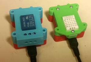
This example shows how to make a temperature sensor controlled ventilator. You will need 2 controller modules. One with DHT shield attached and the other with relay shield.
Once the code has been uploaded, the DHT controller will publish the temperature and humidity values to “temp” and “hum” every 2 seconds. The relay module subscribes to topics “temp” and “conf”. The relay controller will switch the relay if the temperature rises above the set limit (default:28 degrees). To change the set limit, send a new value to the “conf” topic. (For example: “25.5”)
The following is the code for the controller with relay module. Required libraries:
lib_deps = ITTIoT@1.0.5
#include <Arduino.h>
#include <ittiot.h>

// Change it according to the real name of the red IoT module where
// DHT shield is connected
#define DHT_TOPIC "ESP53"

#define RELAY_PIN 5
float t; //for holding the received float value
float tempLimit = 28; //the temperature limit on what the relay will switch

// Message received
void iot_received(String topic, String msg)
{
  t=msg.toFloat();

  // Check if topic contains conficuration data
  if(topic == (DHT_TOPIC"/conf"))
  {
    //re-configures the limit temperature
    tempLimit=t;
  }

  // Check if topic contains temperature data
  if(topic == (DHT_TOPIC"/temp"))
  {
    // Relay switching according to the temperature limit value
    if(t >= tempLimit)
    {
      digitalWrite(RELAY_PIN, HIGH);
    }
    else
    {
      digitalWrite(RELAY_PIN, LOW);
    }
  }
}

// Function started after the connection to the server is established.
void iot_connected()
{
  // Send message to serial port to show that connection is established
  Serial.println("MQTT connected callback");
  // Subscribe to get temperature and temperature configuration messages
  iot.subscribe(DHT_TOPIC"/temp");
  iot.subscribe(DHT_TOPIC"/conf");
  // Send message to MQTT server to show that connection is established
  iot.log("Ventilator example!");
}

void setup()
{
  // Initialize serial port and send message
  Serial.begin(115200);
  Serial.println("Booting");

  // print IoT json config to serial
  iot.printConfig();
  // Initialize IoT library
  iot.setup();

  // Initialize relay pin as output
  pinMode(RELAY_PIN, OUTPUT);
}

void loop()
{
  // IoT behind the plan work, it should be periodically called
  iot.handle();
  delay(200);
}
The following is the program code for the controller with DHT module. Required libraries:
lib_deps = ITTIoT@1.0.5, DHT sensor library, Adafruit Unified Sensor
#include <Arduino.h>
#include <ittiot.h>
#include <DHT.h>

#define DHTPIN D3     // Pin where DHT shield is connected. Change this to D4 if your shield has no legs removed.
#define DHTTYPE DHT22   // DHT 22  (AM2302)

// Create an object for DHT sensor
DHT dht(DHTPIN, DHTTYPE);

// Message received
void iot_received(String topic, String msg)
{

}

// Function started after the connection to the server is established.
void iot_connected()
{
  // Send message to serial port to show that connection is established
  Serial.println("MQTT connected callback");
  // Send message to MQTT server to show that connection is established
  iot.log("IoT DHT example!");
}

void setup()
{
  // Initialize serial port and send message
  Serial.begin(115200);
  Serial.println("Booting");

  // print IoT json config to serial
  iot.printConfig();

  // Initialize IoT library
  iot.setup();

  // Initialize DHT library
  dht.begin();
}

void loop()
{
  // IoT behind the plan work, it should be periodically called
  iot.handle();

  // Read humidity and temperature
  float h = dht.readHumidity();
	float t = dht.readTemperature();

  // Create a buffer to store strings to being sent later
  char buf[10];

  // Convert messages to strings and send to the MQTT server
	String(t).toCharArray(buf,10);
  iot.publishMsg("temp",buf);
	delay(1000);

	String(h).toCharArray(buf,10);
  iot.publishMsg("hum",buf);
	delay(1000);
}


