This is an old revision of the document!
Table of Contents
Afficheur 7 segments à LED
Necessary knowledge: [HW] User Interface Module, [LIB] Delay, [LIB] 7-segment LED Display, [PRT] Light-emitting Diode
Connaissances nécessaires: [HW] digi, [LIB] delay, [LIB] segment_display, [PRT] Diode électroluminescente
Théorie
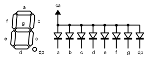
L'indicateur de nombres à 7 segments de LED est un afficheur qui est constitué de 7 LEDs positionnés en forme du chiffre 8. En allumant ou éteignant les LEDs correspondantes, i est possible d'afficher les chiffres de 0 à 9 ainsi qu'un bon nombre de lettres.
Electriquement toutes les anodes des LEDs sont connectées à la broche de l'anode ca. Les LEDs s'allument en inversant la position de leur cathode (a, b, c…). Il existe aussi des connections inversées, où les indicateurs ont une cathode commune cc. Habituellement la plupart des indicateurs de nombres sont utilisés pour afficher des nombres multi numériques - pour ce faire les indicateurs sont équipés d'un segment point dp. En tout et pour tout un indicateur est composé de 8 segments, mais il continu d'être appelé afficheur à 7 segments en accord avec le nombre de segments.
L'afficheur de nombre à LED est très facile à utiliser, il peut être contrôlé directement à partir des broches du micro-contrôleur, mais il existe des drivers spéciaux qui sont capable de contrôler l'afficheur en utilisant moins de broches du micro-contrôleur. Il existe différentes couleurs d'afficheurs qui peuvent être très brillantes et très larges. Enfin, il existe des afficheurs spécifiques composés de segments supplémentaires permettant d'afficher les caractères de l'alphabet Latin.
Pratique
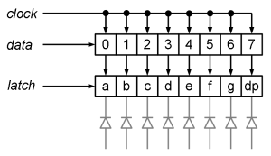
Il y a un afficheur 7 segments disponible sur la carte du module numérique. Il est contrôlé par l'intermédiaire de l'interface en série A6275. L'interface en série est similaire à SPI, où on utilise les signaux de l'horloge et les signaux de donnée. Contrairement à SPI la fonction chip-select n'est pas utilisée ici, nous la remplacerons par la fonction latch. Les trois voies mentionnées ci-dessus sont connectées à ATmega128 comme suit:
- Latch-signal (latch) - PG2
- Clock-signal (clock) - PC7
- Data-signal (data) - PC6
The data is delivered by bits through the data pin. Every time the clock signal goes high, the contents of the shift-index is shifted to the right and the bit from the data-pin is read to the left most cell. By this 8-bits are loaded to the shift-index. If the latch signal is set high, the value of the shift-index is loaded to the latch-index, where it remains until new loading. Each bit of the latch-index is connected through the current switching to one number-indicator’s segment. The segment is lit during the high bit-rate.
For displaying the numbers on the Home Labs digital modules´ indicator, the following functionality is writen to the library of the Home Lab.
//
// Set-up of the pins
//
static pin segment_display_latch =    PIN(G, 2);
static pin segment_display_data_out = PIN(C, 6);
static pin segment_display_clock =    PIN(C, 7);

//
// Marking card.
// The bits are marking the segments. Lower ranking is A, higher ranking is DP.
//
static const unsigned char segment_char_map[11] =
{
	0b00111111,
	0b00000110,
	0b01011011,
	0b01001111,
	0b01100110,
	0b01101101,
	0b01111100,
	0b00000111,
	0b01111111,
	0b01100111,
	0b01111001   // E like Error
};

//
// Start-up of the 7-segment indicator.
//
void segment_display_init(void)
{
	// Set latch, data out and clock pins as output
	pin_setup_output(segment_display_latch);
	pin_setup_output(segment_display_data_out);
	pin_setup_output(segment_display_clock);
}

//
// Displaying number on the 7-segment indicator.
//
void segment_display_write(unsigned char digit)
{
	unsigned char map;
	signed char i;

	// Check-up of the number
	if (digit > 9)
	{
		digit = 10;
	}

	// Number as the card of the segments.
	map = segment_char_map[digit];

	// Latch-signal off
	pin_clear(segment_display_latch);

	// Sending he bits. Higher ranking goes first.
	for (i = 7; i >= 0; i--)
	{
		// Setting the pin according to the value of the bit of the card.
		pin_set_to(segment_display_data_out, bit_is_set(map, i));

		// The clock-signal as high for a moment.
		pin_set(segment_display_clock);
		_delay_us(1);

		// The clock-signal as low.
		pin_clear(segment_display_clock);
		_delay_us(1);
	}

	// Latch-signal on.
	pin_set(segment_display_latch);
}
For displaying numbers and the letter “E”, is created a constant array segment_char_map, where lighting of all 8 segments is marked with bit 1 and switch off is market with bit 0. The bits form higher to lower (from left to right in binary form) are marking segments DP, G, F, E, D, C, B, A. The control interface of the driver is realized through software SPI, i.e. by using a software for controlling the data communication pins in the program. All three pins are set as output with segment_display_init function. segment_display_write is for displaying the function, which finds the segment-card of the mark from the array and transmits bit by bit all values of the segments to the driver. The frequency of the clock signal with the software delays is now approximately 500 kHz.
The following is a more concrete example of a program for using the number-indicator. Previously described function of the library is described in the program. The program counts numbers from 0 to 9 with approximate interval of 1 second. Such counting is achieved by taking a module from a much larger number.
//
// The example program of the 7-segment LED indicator of the Home Lab's
// input-output module.
//
#include <homelab/module/segment_display.h>
#include <homelab/delay.h>

//
// Main program.
//
int main(void)
{
	int counter = 0;

	// Set-up of the 7-segment indicator.
	segment_display_init();

	// Endless loop.
	while (true)
	{
		// Displaying the ones values of the counter.
		segment_display_write(counter % 10);

		// Counting very long.
		counter++;

		// Delay for 1 second.
		sw_delay_ms(1000);
	}
}


